
RF circuits is probabily the field in electronics that have always fascinated me the most. The first time I approached it so many things felt like magic. Then once I start understanding the basic concepts it felt even more magic. When I was in 3rd grade at highschool, I was studying informatics and telecomunications and needless to say I really wanted to build my own RF transmitter and receiver out of discrete components to really see how things work. Thats what this project was all about: trying to draw the schematics and build the circuits from scratch to see if I got the basics right.
Overview
For the carrier I choose 27.145MHz cause it’s a free band (at least in Italy) and it’s a good compromise of a not to high frequency (I can see it pretty easily with my 100MHz oscilloscope) and not too low to need longer antennas.
The ultimate goal was to build an audio transmitter and receiver using AM modulation
Transmitter
Block Diagram

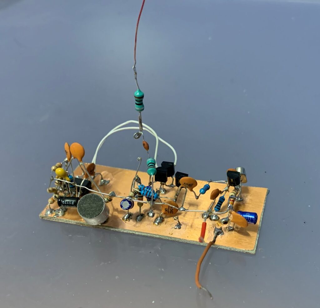
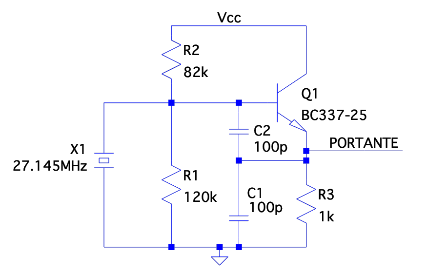
Oscillator
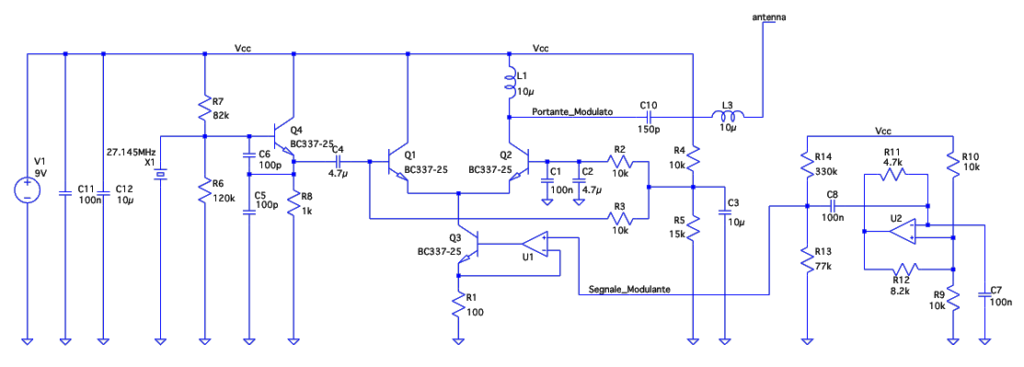
the oscillator is a Colpitt topology with a quartz tuned at 27.145 MHz
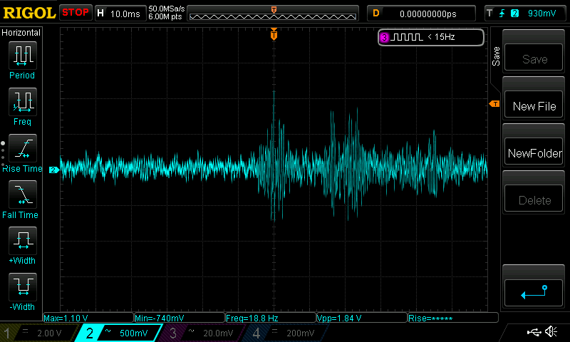
measured generated signal
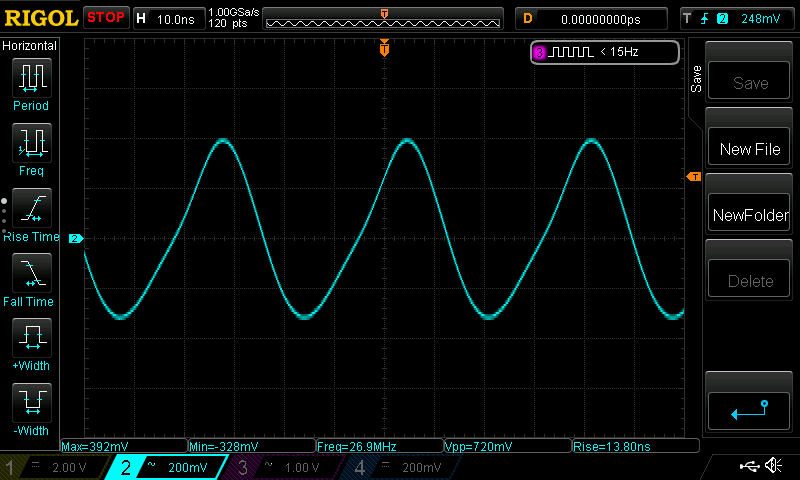
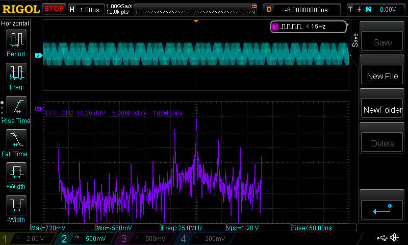
as can be seen by the measurement the generated signal is not perfectly sinusoidal but contains some unwanted harmonics
Audio signal conditioning
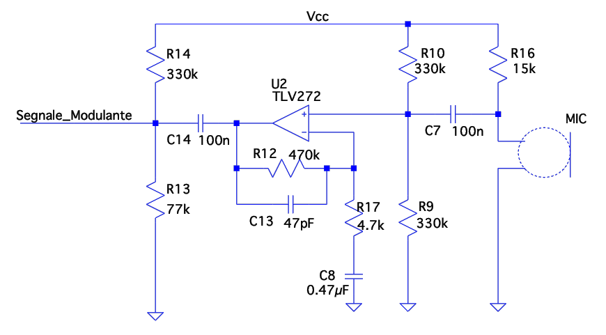
The audio signal transduced by the microphone is amplified and filtered by U2.
- The stage has a gain of 40dB;
- R12, C13 form a Low-Pass filter with cutoff frequency at 17kHz
- R17, C8 for a High-Pass filter with cutoff frequency at 80Hz
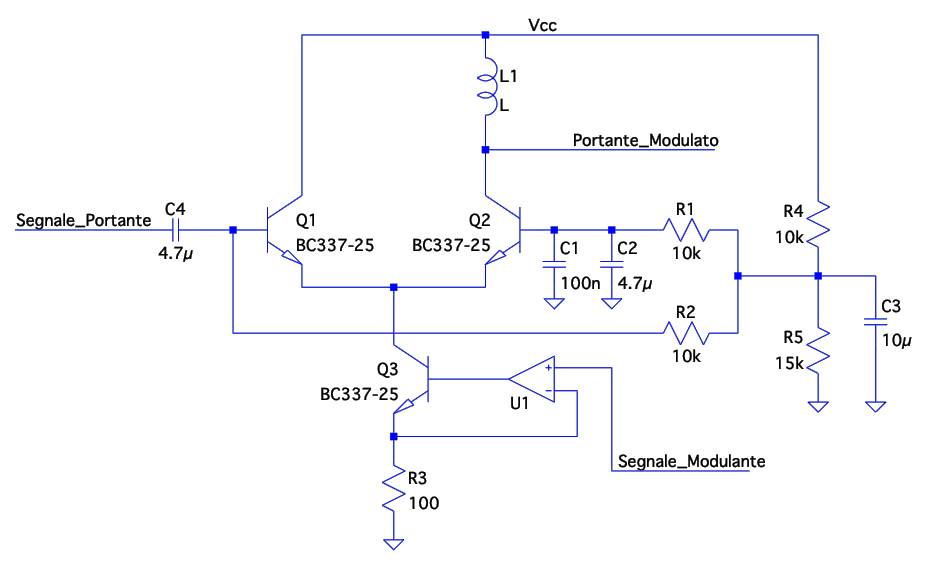
RF Amplifier and Modulator
for both modulation and amplification I decided to use a simple differential amplifier where the modulation is obtained by modulating the differential pair tail current. I choose this topology since it is not affected by miller effect resulting more suitable at RF frequency
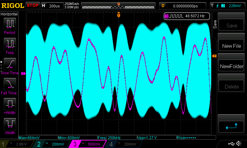
Some measurements of the modulator’s operation
Transmitter Complete Circuit
Receiver
Block Diagram
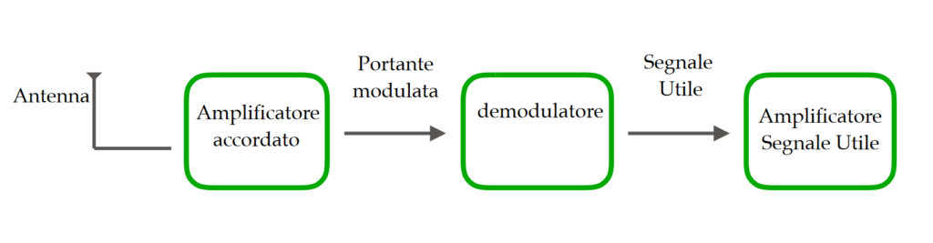
Tuned Amplifier Circuit
The receiver stage is mainly composed by a tuned common-emitter amplifier, tuned of course at 27.145MHz
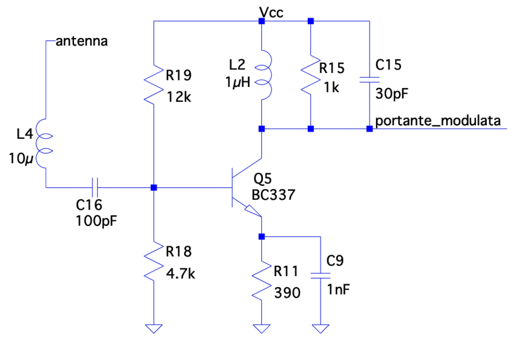
L4 is the antenna tuning inductor and it’s value choice will be documented below
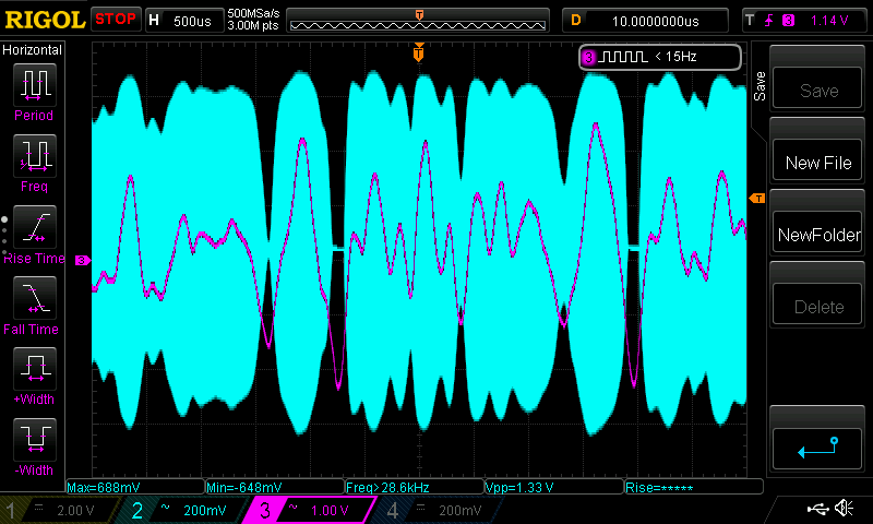
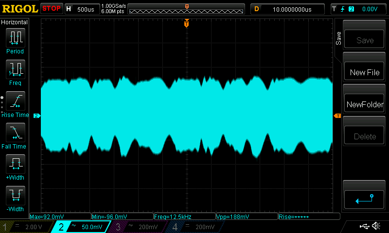
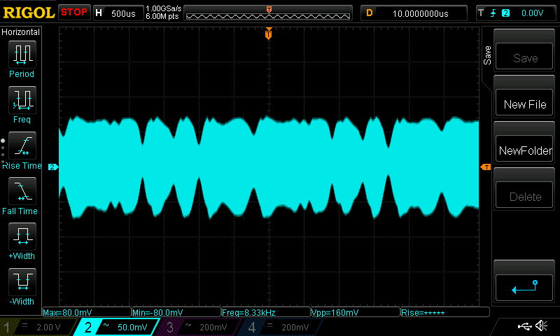
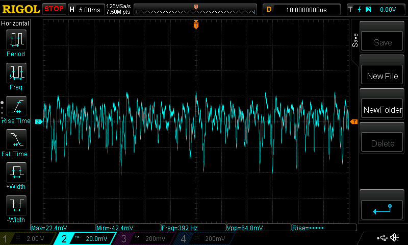
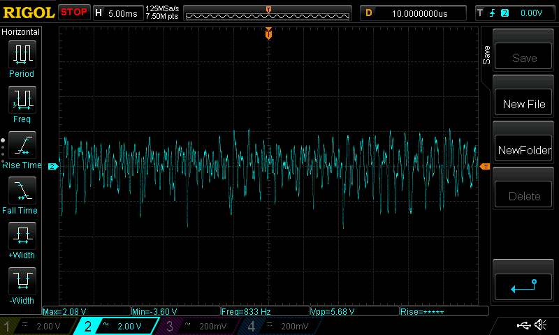
The following are two images of a received and amplificated signal
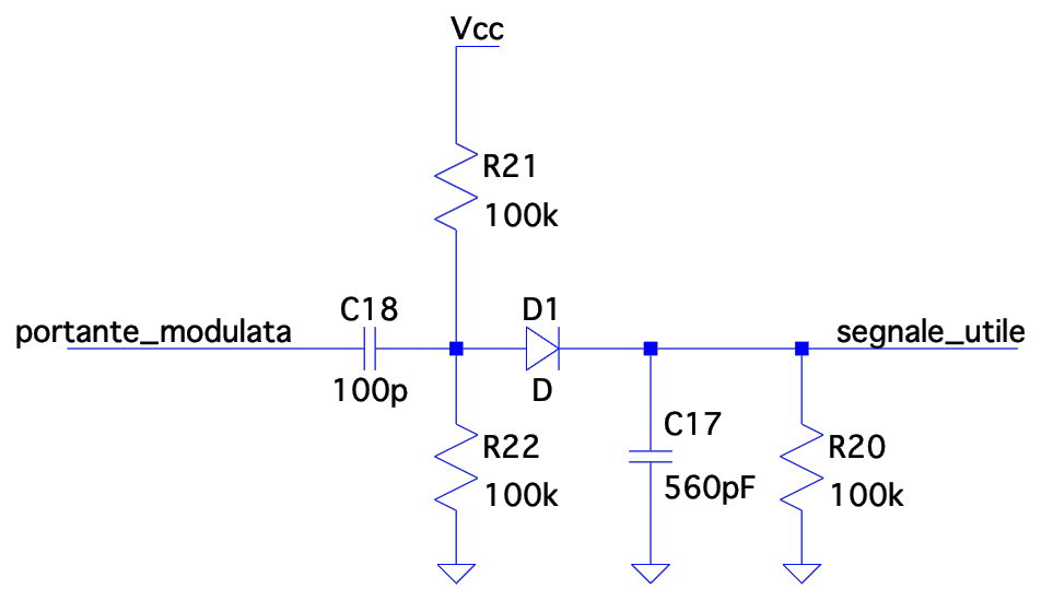
Demodulator Circuit
The demodulator circuit is a simple diode detector
Audio filtering and Amplification Circuit
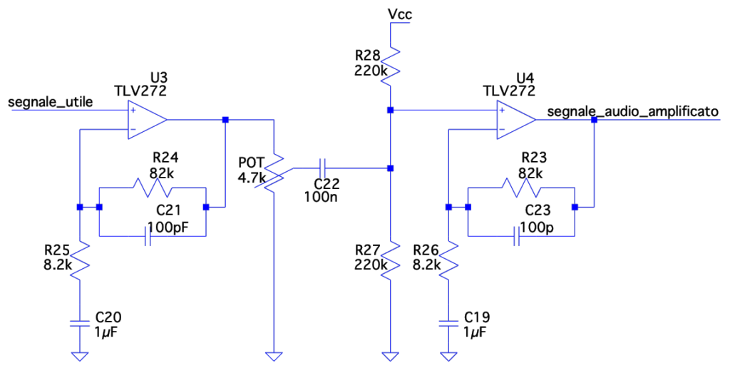
The circuit is very similar to the one used in the transmitter with the difference that two stages are used for acheiving more amplification
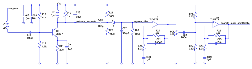
Receiver complete circuit
Antenna Tuning
A quarter-wave antenna at 27.145MHz woudl be 2.62 meters long, which is impratical. I wanted to reduce the antenna length to just 30cm and for this I needed to add an inductor in series with the antenna. However since I didn’t know the characteristics capacitance and inductance of the wire I was using as antenna I decided to adopt a trial and error approach.
To start I cut two pieces of 2.62m long wire, attached one to the transmitter and one to the receiver and measured with the oscilloscope the received signal amplitude. I then substituted the antenna at the receiver with a 30cm long one and tried putting in series different inductors until I matched the amplitude of the signal received with the quarter wave antenna. The value of inductance was 10uH which I then added both at the transmitter and at the receiver

